25 May 2012
Last updated January 1, 2014
NOTES:
This article discusses using 19 volt laptop computer power adapters. This is because those were the ones I was able to obtain. Power adapters rated at 20 volts will also work perfectly. Any power supply with a current rating of 3 amperes or higher will be satisfactory.
The
diagram indicates the use of 1N4007 diodes connected across each power
adapter. It is NOT necessary to use 1N4007 diodes; I just had a lot of
those on hand, so I used them. Any general-purpose rectifier diode with
a peak inverse voltage (PIV) of the 50 V or more with a current rating
of 1 Ampere or more will work satisfactorily. A better diode is a
1N5408. It has a 3 ampere current rating, and is better suited to
handling the overload current which may be supplied during a fault
event, however, no failures of the 1N4007 diodes have been observed.
The Schurter power line filters shown in the schematic diagram are used to reduce the small amount of common mode noise that is always present on the DC output from a switching power supply. While testing the SSQ-2F, this slight noise caused some instability in the traces on my oscilloscope display, so the filters were added during testing to eliminate the interference. In normal operation, these filters are NOT needed. They may be omitted without any problems.
While designing a new RF amplifier for use with the SSQ-2F Rife audio system processor board, I used a heavy-duty variable voltage power supply to power the amplifier during prototype testing. Although I have a large, expensive laboratory power supply that works quite well, the problem was, what could I recommend to researchers who wanted to use the amplifier? After all, they surely would not be happy to pay $2500.00 USD for such a power supply!
The requirements for the power supply I needed for my testing and experiments were that it should be able to supply a well-filtered and regulated DC voltage of between +19 to +190 volts, with a current of up to about 3 amperes. It should be voltage regulated at the chosen voltage, and current limited to prevent destruction of the amplifier should an accident or transistor failure in the amplifier happen. Pretty stiff requirements for a commercial power supply without spending a lot of money, far more than the rest of the entire system would cost. After a comprehensive search of commercially available power supplies, I decided that the easiest and least expensive way to obtain such a power supply would be to construct one. Unfortunately, such a project is beyond the abilities of most experimenters. Something even easier was required.
Since it is a common procedure to "stack" batteries in series to obtain higher voltages, I thought that perhaps I could do the same thing, but using power supplies instead of batteries. Digging through the junk box produced a couple of of laptop computer power adapters. These are purpose-designed units that are designed to work under almost any conceivable service conditions with safety in mind. They are pretty much designed to be bulletproof and idiot proof. Just what I needed! I did a quick bench lash-up and found that they did indeed work together to produce a well-regulated power supply that had twice the voltage of a single power adapter. After a bit of design work, I placed an order for ten more laptop power adapters. After a few days, they arrived and I set to work turning them into a usable power supply.
The plan was pretty simple. All the power mains cables were connected in parallel and plugged into the mains outlet. All of the output wires from the power adapters were connected together in a series configuration, so that all of the output voltages would add together to produce the required DC supply voltage. For protection of the individual power adapters, I connected a diode across the individual power output connections of each power adapter. The diodes act to prevent any reverse current from flowing through an individual power adapter should that adapter fail to start correctly at turn-on, or should it shut down due to an overcurrent or overload condition. All of the power adapters, the terminal strips and the voltage selector switch were mounted on a length of wooden board which was painted black to match the power adapters. Plastic wire ties were used to form a compact cable bundle of the mains cables and the ten output cables from the power adapters in order to make things look somewhat neater.
Although this particular configuration does not give a continuously adjustable DC output voltage, the steps of 19 V that are obtained with these particular laptop power adapters are sufficiently close together to allow selection of a "close enough" supply voltage for the amplifier to operate correctly. After construction, the completed power supply proved to be more then adequate for testing and ordinary day-to-day use.
One note of caution: laptop power adapters commonly come with two types of eight AC mains power cables. One style has only two conductors in the power cable, and the other style has three conductors. The third conductor is used for the earth or ground connection. Of the several types of laptop power adapters I tried, the two-wire adapters all worked together with no problems. However, the three-wire adapters were unhappy, and refused to function properly with their neighbors until the earth wire was disconnected and isolated (not used.). In the photographs you see below, you will notice that the yellow and green earth wires have been disconnected at the terminal strip. They are not connected to anything.
Circuit diagram of the power supply. Click here for a PDF copy of this diagram.
The use of the common mode noise filters is optional, but some laptop power adapters put out enough RF noise to cause difficulties in the logic circuits of the SSQ-2F. The use of an oscilloscope to observe the waveform from the SSQ-2F will disclose any problems due to noise on the power supply lines.
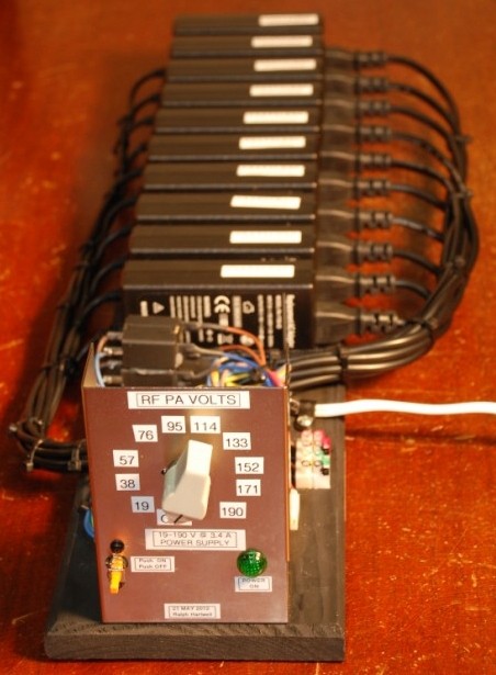
This view of the power supply shows the PA voltage selector switch.
In the background you can see the stack of ten laptop adapter power supplies. Just to the front of the power supplies are the to common mode noise filters. I included then in my power supply because of my strict requirements for the testing sequences I perform when I am qualifying new circuit designs
The use of these noise filters is not required for normal operation and they may be omitted without affecting system performance.
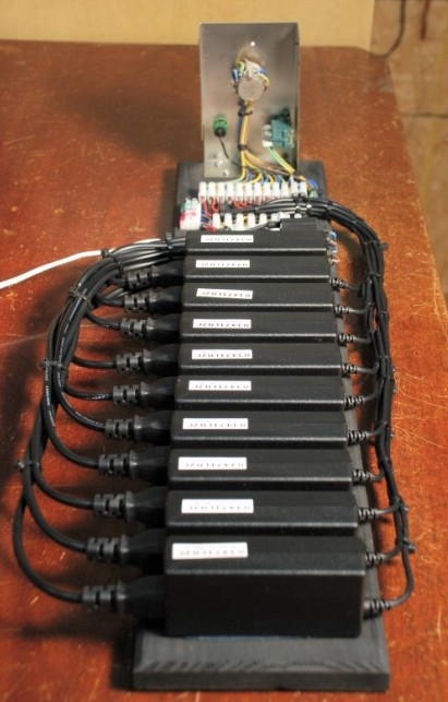
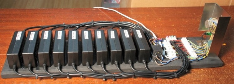
Looking at the power supply from the rear.
All of the laptop adapter power supplies are attached to a piece of wood in the board by the use of RTV silicone adhesive. A gap of about 1/2 inch is left between each power supply to allow cooling air to flow between the units. The AC mains power cables are visible on the left-hand side of the each power supply and the DC power cables exit the supplies from the right side.
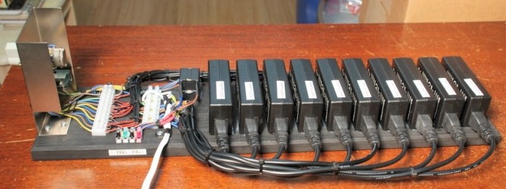
A right side view of the power supply.
The two common mode noise filters are visible just to the left of the laptop adapter power supplies. The white plastic terminal strip closest to the common mode noise filters is used to interconnect all of the AC mains wires. The white plastic terminal strip closest to the voltage selector switch is used to interconnect all of the DC outputs of the power supplies. 1N4007 protection diodes are connected across each power supply at this terminal strip. The white cord exiting the side of the unit is the AC mains cable.
A left side view of the power supply.
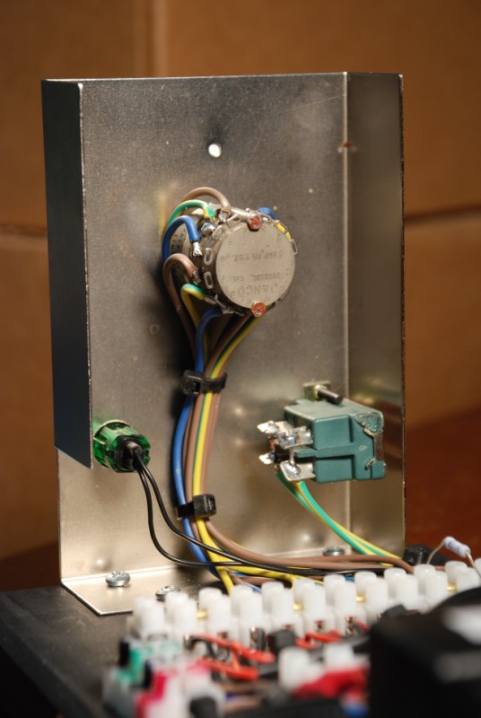
The metal control panel contains a rotary switch which allows selection of the different output voltages as required by the amplifier. A green indicator light is connected across the output of the first power supply in the string. This light indicates that DC output power is available. The AC mains power is switched on and off using the green switch at the right side of the picture.
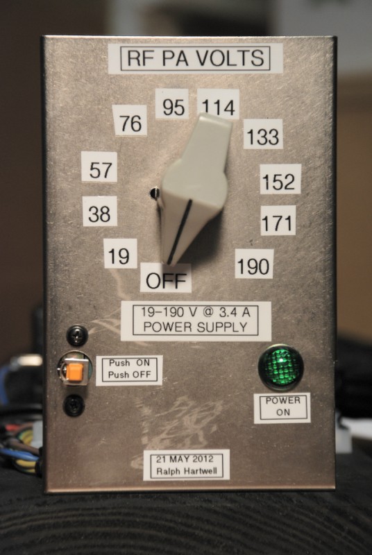
A front view of the control panel.
The PA output voltage is switch selectable in increments of 19 V. This allows the power supply to produce voltages between 19 and 190 V at a maximum current of 3.4 A. Because each power supply is current limited, a short circuit or failure in the amplifier will not result in destruction of the power supplies. If you are using power adapters that are rated at 20 volts, then your output voltage steps will be be increments of 20 volts, i.e., 20, 40, 60, 80, 200, 120, 140, 160, 180, and 200 volts.
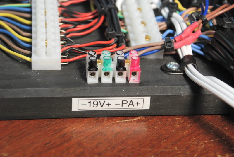
The DC power output terminal strip.
+ 19 volts DC is taken from the first power supply in the string of ten power adapters to provide the necessary DC power for the logic circuits and also to supply power for the IRF730 MOSFET RF amplifier in the SSQ-2F v3.10 which is used to provide RF drive to the PA1 amplifier. DC power for the PA1 amplifier is taken from the PA power connections at the right hand side of the terminal strip. if you look closely you can see several of the 1N4007 diodes connected on the right hand side of the left terminal strip in this picture.
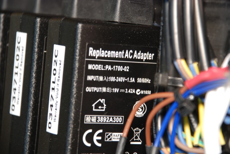
A close-up view of one of the laptop power adapters. This model adapter is commonly available on the Internet at prices under $10 USD. Almost any other power adapter can be used, as long as each of the adapters has the same voltage and current rating as the others.
Please note that the physical configuration and layout of the completed power supply as shown in this article is only one way to construct the unit. I built my version in this configuration because it was simple to build, fast to construct, and easy to repair should something fail. You may construct your power supply in any manner you choose. Should you decide to put the unit inside a cabinet, please ensure that there is adequate airflow through the enclosure to properly cool the power adapters since they do get warm in a normal operation.
There are also available some other close up photos of this power supply showing the terminal strips, the protective diodes and other components. Click HERE and your browser will open the directory where the photos are stored. Please click on each file name to display the individual photos.

This web site and all contents including pictures, text and diagrams is Copyright © 2012 - 2014 by Ralph M Hartwell.
All Publication, Reproduction and Manufacturing Rights Reserved.