 Rife Plasma System Components Rife Plasma System Components
Information current as of 03 December 2017
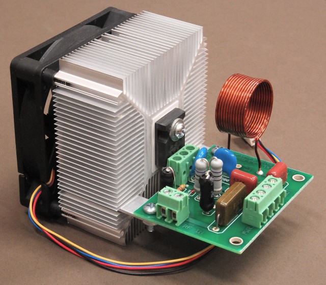
The PA1 amplifier with the HS2 heat sink.
Designed
to operate with the SSQ-2F v3.21, the PA1 is a specially designed high
power Rife Plasma tube amplifier.
The
price of the PA1 ssembled and tested, with HS2 heat sink
& fan is $175.00.
|
The PA1 is a high-frequency switch-mode power supply designed to convert DC power into semi-square wave pulses of energy at 3.1 MHz at power levels sufficient to drive the largest plasma tube. The PA1 has been designed so that its output matches a standard 50-ohm load impedance, making it possible to connect the output of the PA1 to a conventional antenna tuner or to the our LC31 coupler system. The PA1 with its innovative design amplifies the high quality signal from the SSQ-2F v3.21. The PA1 is designed to be driven by the SSQ-2F v3.21. The PA1 increases the power output of the SSQ-2F v3.21 to a power level of between 300 to 500 Watts peak power depending upon the voltage of the DC power supply and the modulation duty cycle. When using a modulation duty cycle of between 0 to 100%, the PA1 will produce at least 300 Watts peak or continuous power output. For a modulation duty cycles between 1 to 50%, the PA1 can produce up to 500 Watts peak power output. These power levels are sufficient to operate even the largest plasma tubes. Please download and read the operating manual for the PA1 before placing your order. It is important to read and understand the information about using an adequate heat sink with the PA1. Although the PA1 is physically very small, it handles a lot of power. Just as with any high power RF amplifier, a substantial heat sink is required for proper operation.
SpecificationsDC Power Supply Input: 1) +15 to +190 V DC at a maximum current of 3.0 amperes. Average operating current less than 2.1 amperes, depending on output power level and modulation duty cycle. 2) +150 V DC required for a nominal peak power output of 300 Watts across a 50-ohm load resistance. 3) +190 V DC required for a nominal peak power output of 500 Watts across a 50-ohm load resistance. Output Load Impedance: 50 ohms. Input Drive Signal: 5 Watts, semi-square wave pulse waveform at 3.1 or 3.3 MHz from the SSQ-2F v3.21. Operating Frequency: 2.8 to 3.8 MHz. Operation outside of this frequency range may cause damage to the PA1. Nominal operating frequency is 3.1 or 3.3 MHz. RF Power Output: 1) The PA1 will produce up to 500 watts peak power, or 250 watts average power across a 50-ohm load when the carrier is modulated by a 50% duty cycle square wave. 2) When operated at a peak power level of 300 watts, the PA1 may be operated with any duty cycle between 0 to 100%. 3) The power output of the PA1 may be adjusted by varying the DC voltage supplied to the PA1. |
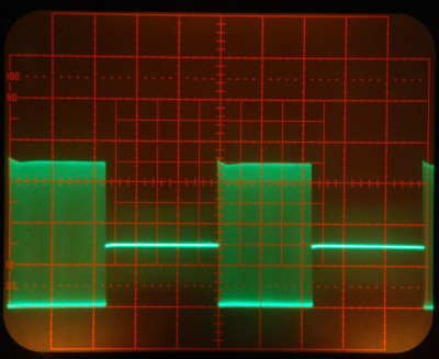
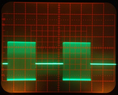
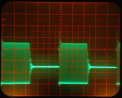
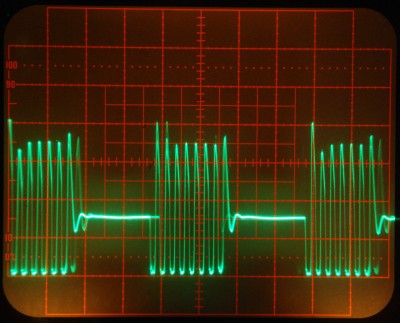
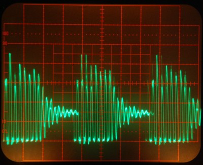
The left side photos are of the PA1 output waveform across a 50-ohm dummy load.
The right side photos are of the PA1 output waveform across a Cheb 8-inch Phanotron tube.
The PA1 was coupled to the Phanotron tube using the 3.1 MHz link coil coupler.
The carrier frequency was 3.1 MHz. The modulation duty cycle was approximately 50%.
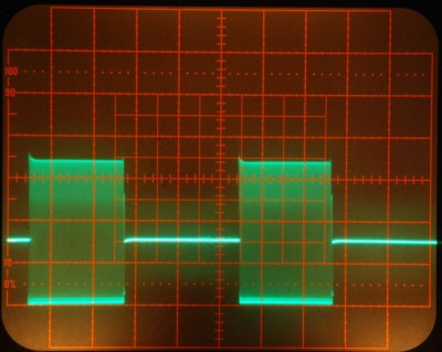
Modulation frequency 20 Hz.
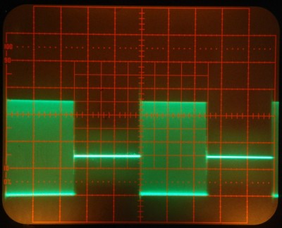
Modulation frequency 2 KHz.
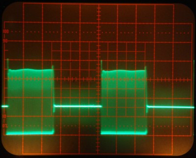
Modulation frequency 20 KHz.
Modulation frequency 200 KHz.
RADIO FREQUENCY WARNING NOTICEThe PA1
is a high-frequency switch mode power supply module designed to furnish
a square wave modulated high voltage alternating current at a frequency
of approximately 3.1 MHz across a 50-ohm load impedance. If the PA1 is
installed incorrectly or used improperly, it is capable of causing
severe radio frequency interference. To prevent this from occurring,
observe the following warnings:
Any
attempt to drive the PA1 with a radio frequency source such as a CB
radio transmitter, will result in either no power output from the PA1
or immediate destruction of the STW20NK50Z MOSFET in the PA1.
|

This web site and all contents including pictures, text and diagrams is Copyright © 2012 - 2020 by Ralph M Hartwell.