 Rife Plasma System Components Rife Plasma System Components
Designed for use as a signal processor in Rife Plasma Tube systems operating at 3.1 MHz, but it will operate over the range of 0.5 to 15.0 MHz.
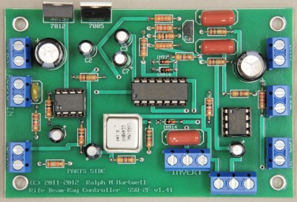
Specially designed to allow square wave modulation of up to 42,000 Hz when using standard computer sound cards.The SSQ-2F Controller generates a square wave modulated 3.1 MHz RF signal which may be sent to an RF amplifier to drive a Rife Plasma tube. Download the Instruction Manual for the SSQ-2F v1.41 HERE The price of the SSQ-2F v1.41 assembled and tested is $125.00. Kit version also available.
Ordering information for the SSQ-2F v1.41 is available on the Products page. |
Overview -
Specifications:Power:
Input Audio Signal Waveform:
Modulation Modes:
Carrier Frequency:
Modulation Frequency Ranges - 2x Mode:Input Audio Frequency Range in 2 X Mode @ 40 - 175 mv p/p input level with a Sine or Triangle Wave input signal:
NOTE: In the 2x mode, using a sine or triangle wave audio input, the output of the Controller Board will maintain a 50% duty cycle ratio to within 10% or less across the input frequency range of 40 to 30,000 Hz at maximum audio gain, or 40 to 60,000 Hz at minimum audio gain. This allows unattended operation of the equipment without the need for constant audio gain adjustments when using an audio sweep signal generated by a computer sound card. It is necessary to maintain a low source impedance and a constant voltage as the audio frequency changes during the sweep. Modulation Frequency Ranges - 1x Mode:Input Audio Frequency Range in 1x Mode, @ 50 - 140 mv p/p input level with a Sine or Triangle Wave input signal:
Modulation Frequency with a Square Wave input signal of 50 - 75 mv p/p and minimum audio gain:Note: Square wave audio is usable in 1 X Mode only, and a 50% duty cycle is output by the Controller Board.
|
SSQ-2F Waveforms
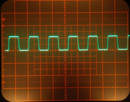
3.1 MHz RF Carrier Oscillator
Lower Trace = 6 KHz audio sine wave input to the SSQ-2F Upper Trace =
Modulated 3.1 MHz RF
Carrier output, modulated at a 6 KHz rate with a 50% duty cycle square
wave.
This is the non-frequency doubled mode of operation of the SSQ-2F.
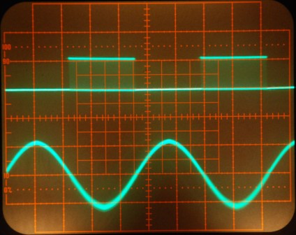
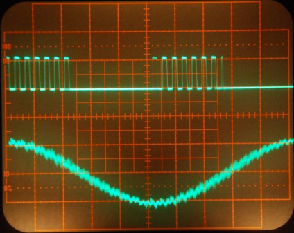
Lower Trace = 6 KHz audio sine wave input to the SSQ-2F Upper Trace = Modulated 3.1 MHz RF Carrier output, modulated at a 12 KHz rate with a 50% duty cycle square wave. This is the frequency doubled mode of operation of the SSQ-2F.
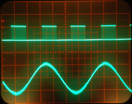
Lower Trace = 194 KHz audio sine wave input to the SSQ-2F Upper Trace =
Modulated 3.1 MHz RF
Carrier
output, modulated at a 388 KHz rate with a 50% duty cycle square wave.
This is the frequency doubled mode of operation of the SSQ-2F. Note that individual cycles of the 3.1 MHz carrier may be seen in the upper trace. Also note the very short rising and falling edges of the modulated 3.1 MHz RF carrier signal.
Same as the above picture, but zoomed in to show the very fast edges of the modulated 3.1 MHz RF carrier signal.
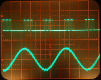
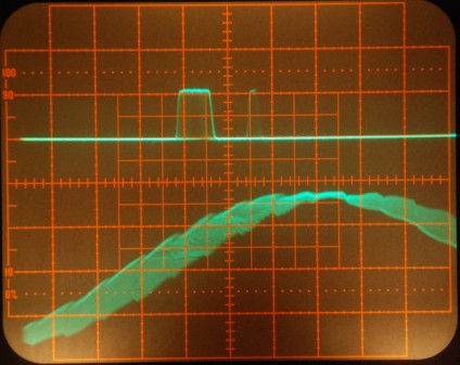
Lower Trace = 155 KHz audio sine wave input to the SSQ-2F Upper Trace = Modulated 3.1 MHz RF Carrier output, modulated at a 310 KHz rate with a 10% duty cycle square wave. This is the frequency doubled mode of operation of the SSQ-2F. Note that there is only one cycle of the 3.1 MHz carrier present in the output. This illustrates the high accuracy of the modulation circuitry of the SSQ-2F. |

This web site and all contents including pictures, text and diagrams is Copyright © 2012 - 2020 by Ralph M Hartwell.
All Publication, Reproduction and Manufacturing Rights Reserved.