Spectrotek Amplifier Selection Guide
Key highlights include:
Power Output: All models produce up to 500 watts of peak power, with a required carrier frequency of 3.10 MHz.
Amplifier Variations: Except for the PA2, all amplifiers include a 3.10 or 3.30 MHz oscillator. The PA2 requires an externally supplied square wave modulated carrier signal within the range of 3.0 to 3.5 MHz.
Programming Input: Most models require an external programming frequency input to generate output. This input is internally converted to a 50% duty cycle square waveform which then modulates the carrier output.
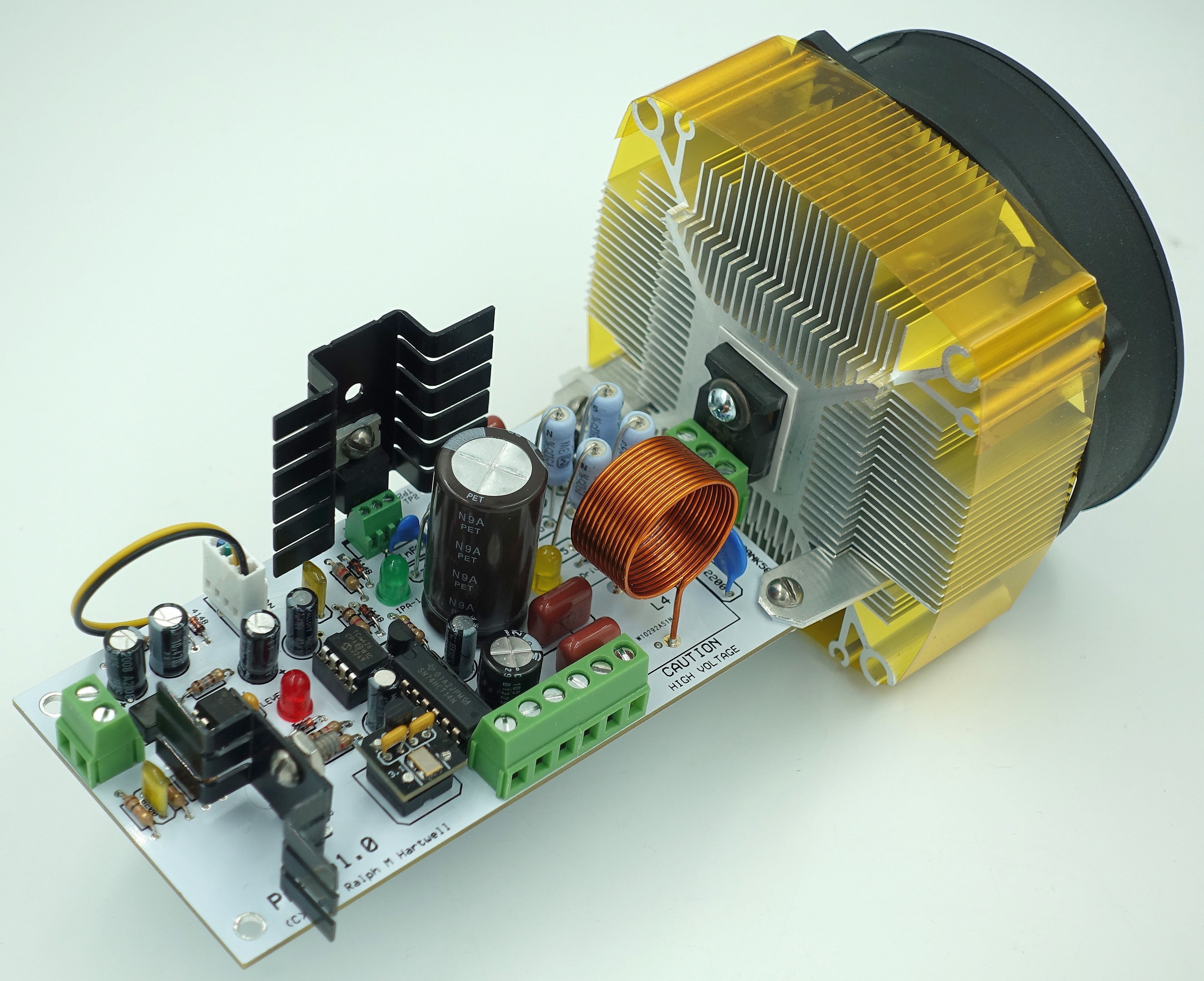
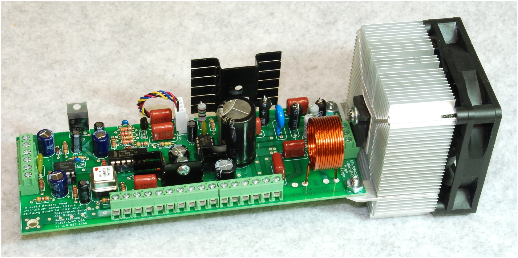
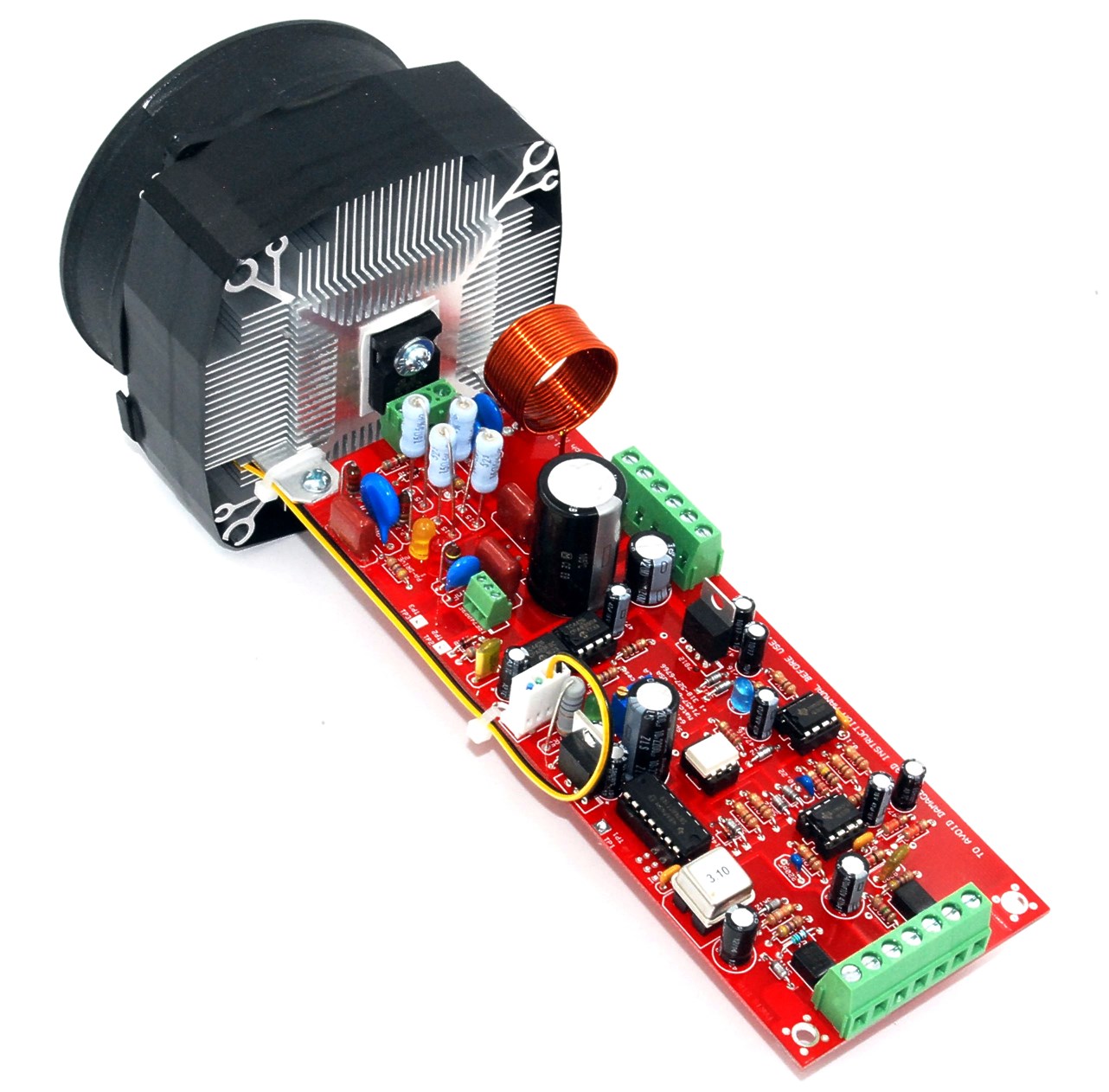
Physical Design: All amplifiers share a similar physical layout, making them interchangeable, although input terminal configurations may differ.
Operational Differences: The primary difference between models is the type of input signal they accept, allowing users to choose based on their available signal generators.
PA2: Suited for users with a 3.1 MHz carrier wave external signal generator.
PA3: Designed for 50% duty cycle square wave input signals from an external signal generator.
PA4: A more flexible model the includes fully automatic operation. The PA4 accepts a wider input signal voltage and waveform range.
SPA5: Fully automatic version, replacing
earlier models SSQ-2F+PA1 and SPA4 for ease of use. The SPA5
is the only amplifier that has the capability of doubling the
audio input frequency before modulating the output carrier
waveform.
Two other devices are available for researchers:
You may download the latest manuals and technical files from our pCloud server at the following links:
https://filedn.com/lLYu7GQm05V4CLoIvC7y464/Spectrotek%20Manuals%20on%20CD/
Or from this short link:
Description of the various Spectrotek amplifiers
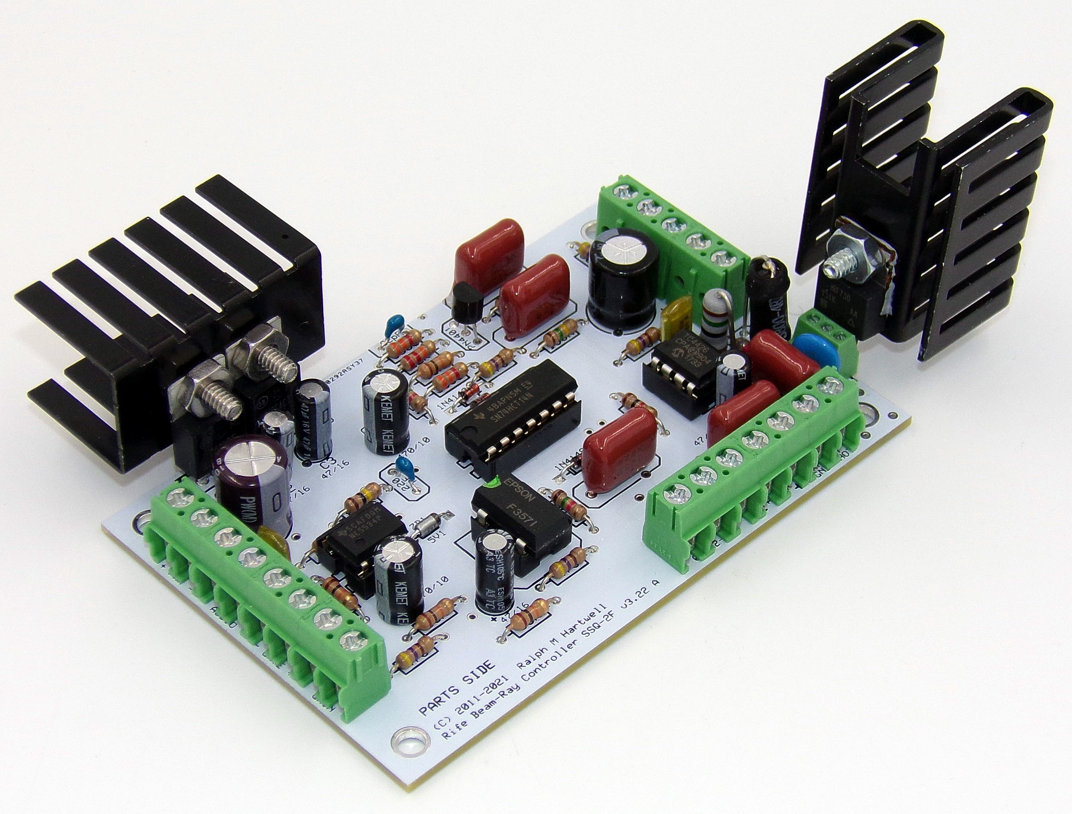
SSQ-2F - (Discontinued but available on Special Order)
The SSQ-2F was designed to accept a sine wave as a signal input and modulate the 3.10 MHz carrier wave output signal with a 50% duty cycle square wave.
To accomplish this, the incoming sine wave was frequency
doubled and then converted to a square wave. A set of on
board jumpers was used to control the direction of the duty
cycle adjustment and to change the input setting from sine
to square wave input signals. The user was required to
monitor system operation using a type M1D duty cycle meter
to maintain the correct output waveform duty cycle.
The power output of the SSQ-2F is about 50 watts, and it can drive a small plasma tube.
PA1 - (Discontinued)
Designed as an add-on amplifier for the SSQ-2F, the PA1 could provide up to 500 watts peak power for driving larger plasma tubes. The combination of the SSQ-2F and the PA1 was discontinued when the SPA4 became available.
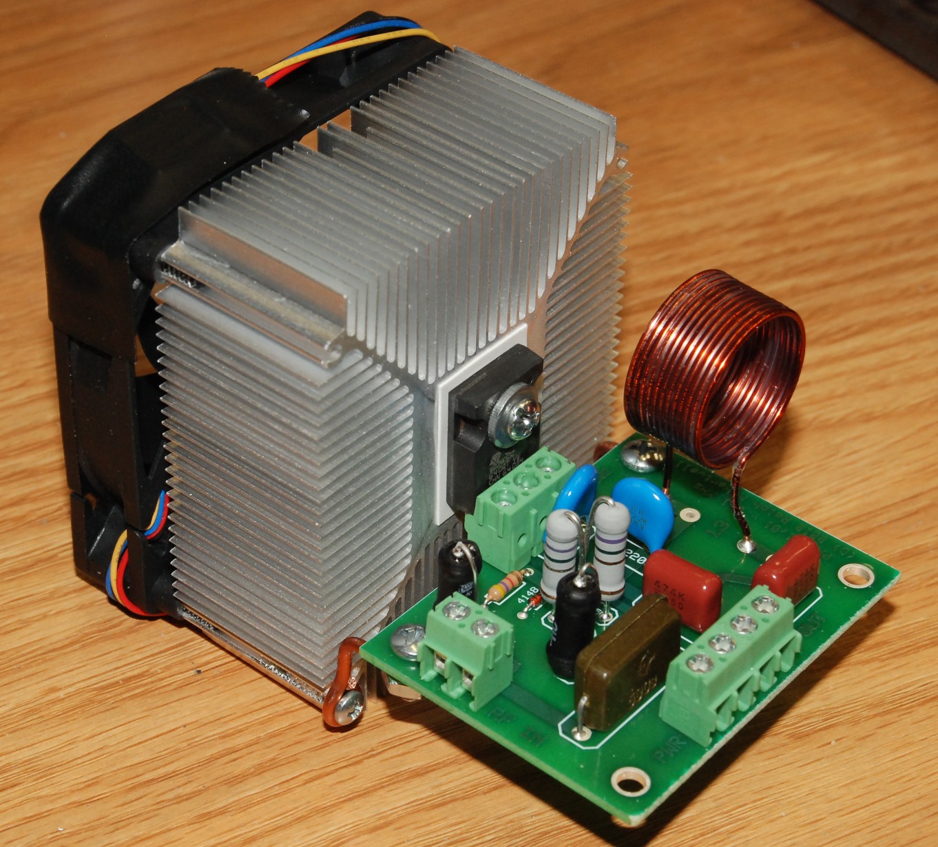
PA2
The PA2 amplifier is designed for the user who has a signal
source such as a GB-4000 which provides a 3.1 MHz carrier
wave which is modulated with the program frequencies they
wish to use. The carrier wave should be a 50% duty cycle
square wave with a voltage level of 5 to 10 volts. Note that
the duty of the output signal will follow the duty cycle of
the input signal.
Most GB-4000 users have switched to using the PA3 and set
their GB-4000 to square wave audio output as this is
considerably easier to make work properly than using the
PA2. When using the PA2 with the GB-4000, it was necessary
to considerably modify the GB-4000. When using the
PA3, no modifications to the GB-4000 are required.
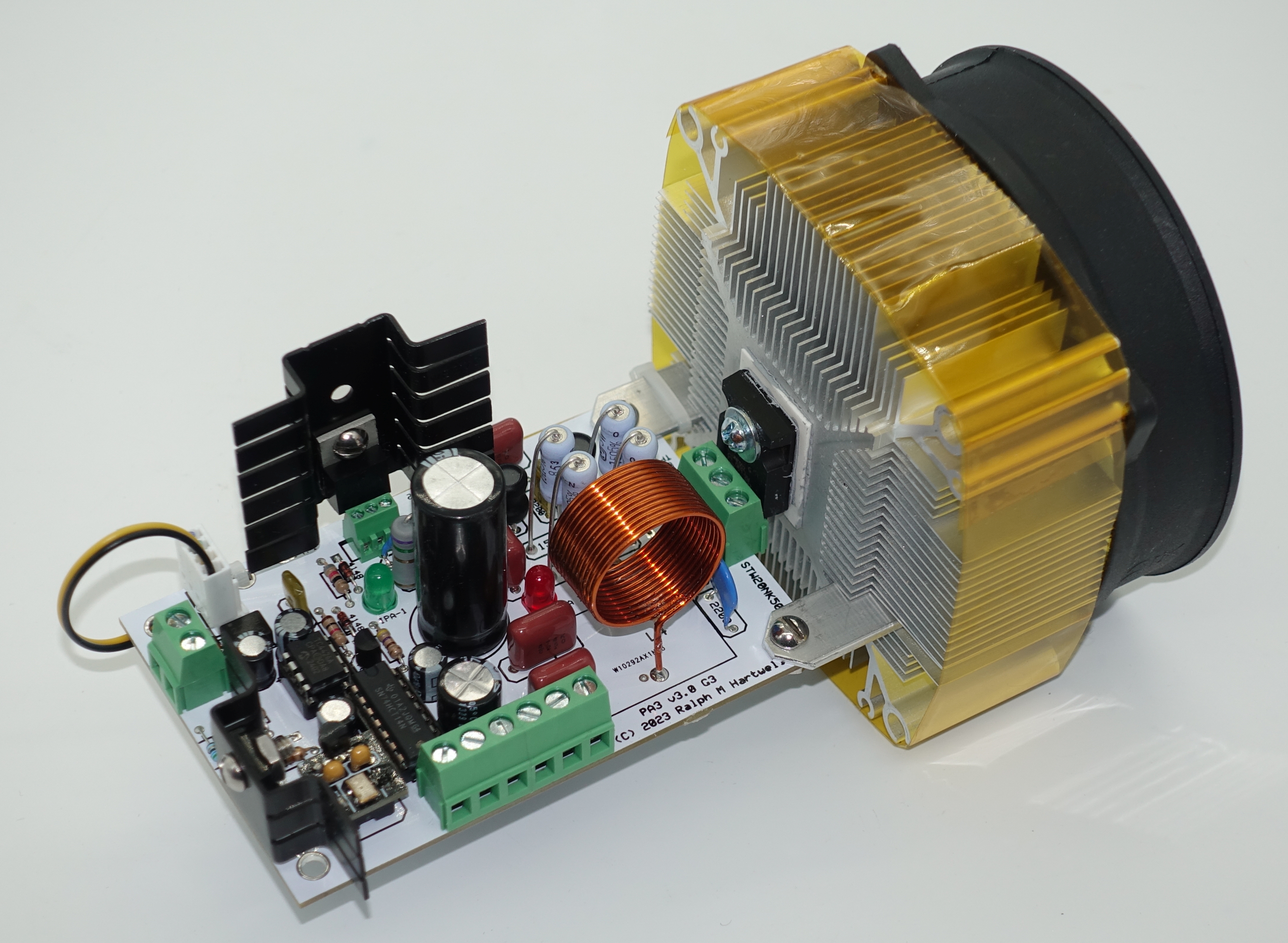
PA3
The PA3 amplifier is designed for use with almost any external frequency or signal generator that can output a zero referenced, positive going, 50% duty cycle square wave with a peak voltage level of 5 to 10 volts.
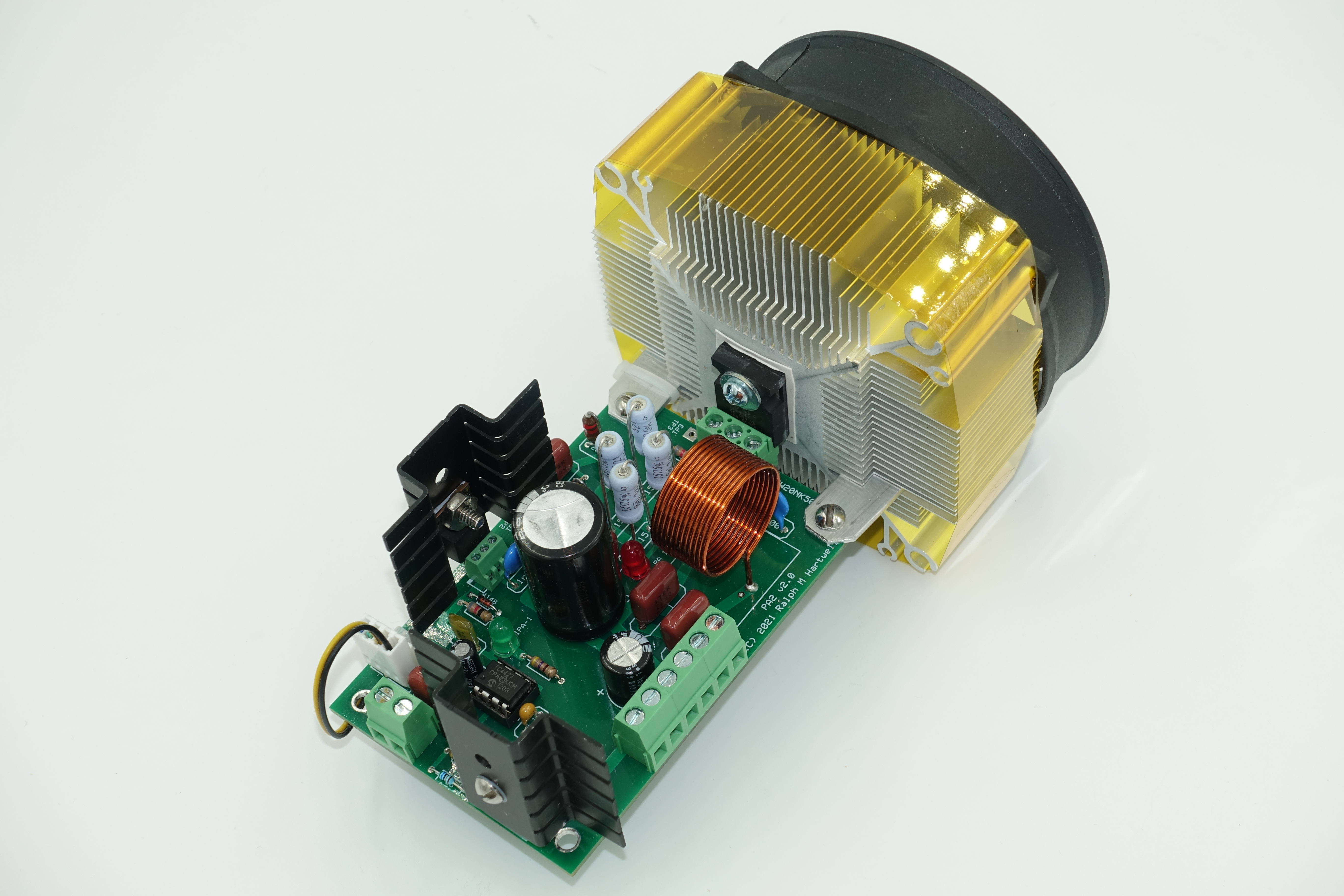
PA4
The PA4 is similar to the SPA5 in that it is fully
automatic and will hold a steady 50% duty cycle square wave
modulation of the carrier.
The operational differences from the SPA5 are:
No jumper changes are required to change from sine wave to square wave input signals as there is only one signal input connection;
The input signal voltage range has been expanded downwards to less than 0.3 volts to allow devices such as cell phones and computers to drive the PA4 without the need to amplify the input signal before sending it to the input of the PA4;
The input frequency is not doubled when using sine waves.
Input modulation signal waveforms of sine, square, trapezoid, and triangle are supported; however they will all be converted to a 50% duty cycle square wave for modulation of the carrier.
There is only one input signal connection and no jumper changes are required when changing the type of input signal.
SPA4 - (Discontinued)
The SPA4 was derived from the SSQ-2F + PA1 amplifier combination. It was designed to accept either a square wave or a sine wave as a signal input and modulate the 3.10 MHz carrier wave output signal with a 50% duty cycle square wave. To accomplish this with a sine wave input signal, the incoming sine wave was frequency doubled and then converted to a square wave
A set of on board jumpers is used to control the direction of the duty cycle adjustment and to change the input setting from sine to square wave input signals.
With the use of external controls, the user could vary the duty cycle of the square wave over a range of about 5% to 95%. However, this required the user to constantly monitor the voltage level of the input signal using a type M1D duty cycle meter or else the duty cycle would change up or down as the input signal voltage changed.
Because this proved inconvenient in practice and somewhat complicated in the construction of a complete system and the fairly high learning curve of the SPA4, a simpler system was needed, and thus the SPA5 was developed.
SPA5
The SPA5 is the fully automatic version of the SPA4. No operator intervention is required to adjust the duty cycle. Simply connect the input modulation signal, and turn on the power to the amplifier.
On Input “A”, the SPA5 will accept a sine wave modulating frequency signal. With a sine wave signal input, the SPA5 performs frequency doubling of the input frequency, just as does the SPA4.
On the “B” input, the SPA5 will accept a modulating frequency source that is a 50% duty cycle square wave with a voltage level of 5 to 10 volts. Note that the duty of the output signal will follow the duty cycle of the input signal. Square wave input frequencies are not doubled.
Note that the PA4 will generally replace the SPA5 for most users.
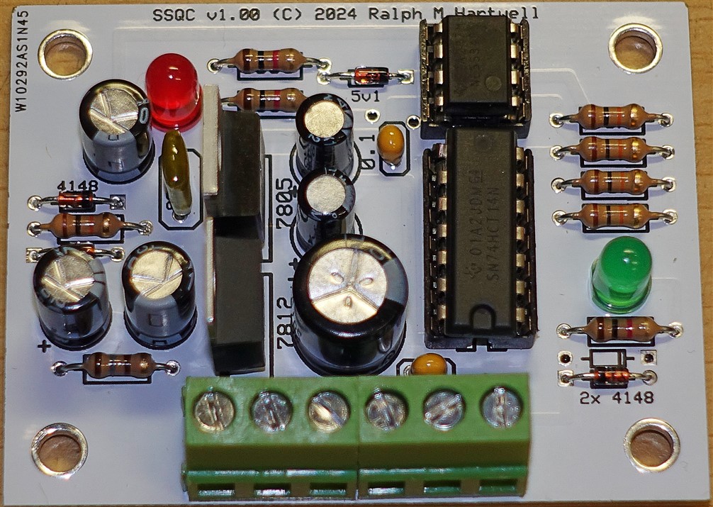
SSQC
Users who have a PA3 amplifier and wish to upgrade its operation to that of the PA4 may use the SSQC. This small circuit board is connected between the modulation signal source and the input of the PA3 amplifier. After this is done, the PA3 + SSQC will operate together as though it were a PA4 amplifier.
Power for the SSQC is obtained from the same +19 volts that powers the PA3.
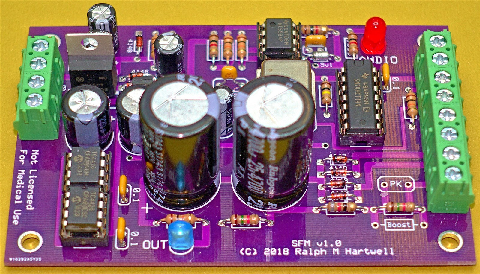
Something Extra – The SFM contact device
While it is not a high power amplifier, the SFM was designed at the suggestion of Ken Uzzell as a replacement and upgrade for his discontinued PFA-2 DIY and PFA-7 contact device units. Unlike Ken’s units, the SFM also allows the use of a carrier wave in the device output.
Some SFM specifications are:
Input Signal:
0.1 to 10.0 volts peak-to-peak with a frequency range of 1,000 Hz to 50,000 Hz with a sine wave input signal, or,
2.0 volts to 10.0 volts peak to peak with a frequency range of 0.1 Hz to 200,000 Hz.
The optimum audio voltage is from 2.0 to 5.0 volts peak to peak.
RF Carrier Frequency:
1.0 to 5.0 MHz. The SFM is shipped with a 3.10 MHz oscillator, but customer selected frequencies may be specified at the time of order.
The carrier frequency of the SFM may be changed by plugging in a different frequency oscillator module.
Output voltage is 16 volts peak to peak, switch selectable for a positive or negative waveform or bipolar AC
Output current user adjustable from approximately 1.2 to 5.3 mA into a 1500 ohm load.
The output signal is switch selectable for audio square wave only, or audio square wave plus 3.1 MHz carrier wave.
Over the specified input frequency and input voltage range, the output waveform is a square wave with a duty cycle of 50%, +/- 3% or less.
For prices and ordering
information about our amplifiers and other products, please
Order Here
All instruction manuals and technical data files for these amplifiers and any of our other products may be downloaded from our pCloud server at either of these links:
https://filedn.com/lLYu7GQm05V4CLoIvC7y464/Spectrotek%20Manuals%20on%20CD/