PA3 Rife Plasma Tube Amplifier with HS5 Heat Sink and Fan
Works with the Spooky2, UDB1108S, GB-4000 or any signal generator with a 0 to +5 volt output
( Click on the picture for a larger view )
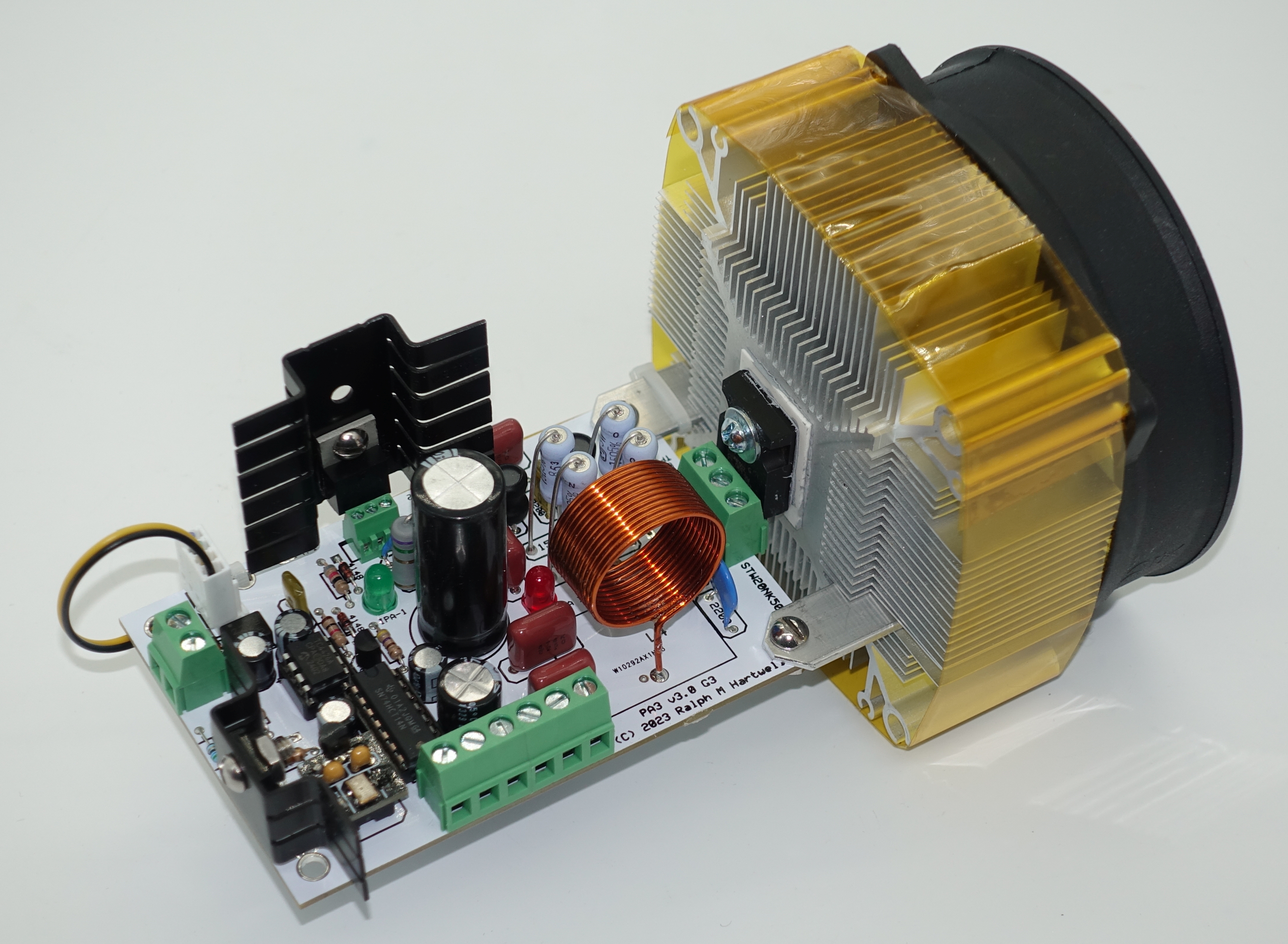
The 500 watt PA3 plasma tube amplifier is furnished assembled and tested, complete with a high-efficiency fan-cooled heat sink assembly.
The PA3 amplifier is designed to be driven by any general purpose signal generator which generates a duty cycle modulated square wave TTL output signal of 0 to +5 volts amplitude.
The PA3 may also be driven by any frequency generator that outputs an audio sine wave signal with a peak-to-peak amplitude of 4.5 to 7.5 volts.
The PA3 generates its own 3.1 MHz carrier signal. It is designed to be used with wide-range audio frequency generators.
Audio Modulation frequencies between 4 and 400,000 Hz may be used at full power. Higher modulation frequencies are usable at reduced power output.
The powerful but quiet cooling fan mounted on the rugged HS2 heat sink allows the PA3 to be operated at full power for as long as the researcher desires. A separate power supply for the cooling fan is not needed, because the PA3 provides power for the fan.
The PA3 is fitted with the Quick Change option, so the power amplifier MOSFET may be easily and rapidly replaced should the need arise - no soldering is required.
Two power supplies are required to operate the PA3, one supply of +20 volts for the logic circuitry and cooling fan, and another of between +50 to +175 volts, depending on the type of plasma tube being used. Please refer to the operating manual for full technical details.
The powerful but quiet cooling fan mounted on the rugged HS2 heat sink allows the PA2 to be operated at full power for as long as the researcher desires. A separate power supply for the cooling fan is not needed, because the PA2 provides power for the fan.
The PA3 is fitted with the Quick Change option, so the power amplifier MOSFET may be easily and rapidly replaced should the need arise - no soldering is required.
Two power supplies are required to operate the PA3 one supply of +20 volts for the logic circuitry and cooling fan, and another of between +50 to +175 volts, depending on the type of plasma tube being used. Please refer to the operating manual for full technical details.
The PA3 has been designed so that its output matches a standard 50-ohm load impedance, making it possible to connect the output of the PA3 to a conventional antenna tuner or to the our LC31 coupler system.
Please download and read the operating manual for the PA3 before placing your order. It is important to read and understand the information about using an adequate heat sink with the PA3. Although the PA3 is physically very small, it handles a lot of power. Just as with any high power RF amplifier, a substantial heat sink is required for proper operation.
- This is a professionally manufactured etched printed circuit board incorporating 3-ounce tin-plated copper traces, and plated-through holes. All parts are high-quality through-hole components.
- Resistors are high stability carbon or metal film, 5% tolerance.
- The PA3 amplifier circuit board is available assembled and fully tested, or as a do-it-yourself kit.
- Screw terminals are provided for all connections to the PA3 - there are no wires to solder!
- 1-year warranty against manufacturing defects.
- Lead-free construction for ROHS compliance.
PA3 Full Technical Specifications:
DC Power Supply Input:
- For the power amplifier stage: +15 to +190 volts DC at a maximum current of 3.0 amperes; nominal operating current less than 2.1 amperes, depending on output power level and modulation duty cycle.
- For the modulation signal processor, the driver stage and the heat sink fan: +18 to +22 volts DC at a maximum current of 750 mA at a 100% duty cycle modulation rate.
Input Impedance:
- 50 or 470 Ohms, user selectable, AC coupled.
Input Drive Signal Requirements:
- TTL level (0 to +5 volts) duty cycle modulated square wave from an external frequency generator.
- Modulation frequency range with square wave input: 4 Hz to 400,000 Hz for a duty cycle range of 1% to 100%.
- Sine wave of 2.5 to 7.0 volts peak-to-peak (VPP) from an external frequency generator. The voltage level of the sine wave adjusts the duty cycle of the PA3 output.
- Modulation frequency range with sine wave input: 4 Hz to 400,000 Hz for a duty cycle range of approximately 20% to 58%.
- The modulation input of the PA3 is AC coupled, so it will ignore any DC offset voltage on the modulation input signal; however any DC offset voltage must be limited to a maximum of +/- 10 volts.
Carrier Operating Frequency:
- 2.9 to 3.5 MHz. Operation outside of this frequency range may cause damage to the PA3. The suggested operating frequency is 3.1 or 3.3 MHz.
- The PA3 is furnished with a 3.10 MHz oscillator, but customer selected frequencies may be specified at the time of order.
- The carrier frequency of the PA3 may be quickly changed by plugging in a different frequency oscillator module.
RF Power Output:
- Up to 500 watts peak power or 250 watts average power into a 50-ohm dummy load when the carrier is modulated by a 50% duty cycle square wave with frequencies from 1 to 400,000 Hz.
- When the PA3 is operated at a peak power level of 300 watts or less, the PA3 may be operated at any duty cycle between 0 to 100%.
- The power output of the PA3 may be adjusted by varying the DC voltage supplied to the PA3.
- To avoid possible damage to the PA3, when driving plasma tubes with modulation frequencies above 40 KHz, the DC power supply voltage to the PA3 should be limited to the maximum values as shown in the data below.
Modulation Signal Voltage Levels:
Note that the PA3 amplifier turns ON when the input drive signal goes in the positive direction, and turns OFF when the input drive signal goes in the negative direction. In the absence of any input signal, the PA3 will turn completely OFF.
Operation of the PA3 with a square wave modulation signal:
A minimum of 2.25 volts-peak-to-peak is required to trigger the PA3. Ideally, the drive signal should be a square wave TTL signal, which has a voltage swing of 0 to +5 Volts.
Modulation Duty Cycle vs. Frequency with a square wave modulation signal:
For a duty cycle of 1% to 50%: 1 Hz to 400 KHz
For a duty cycle of 1% to 89%: 2 Hz to 400 KHz
For a duty cycle of 1% to 98%: 3 Hz to 400 KHz
For a duty cycle of 1% to 99%: 4 Hz to 400 KHz
Operation of the PA3 with a sine wave modulation signal:
A minimum of 2.5 volts-peak-to-peak is required to trigger the PA3 when using sine waves. The maximum allowable sine wave voltage input should be limited to no more than 7.0 volts-peak-to-peak to prevent possible damage to the input circuit of the PA3. When using sine waves, the duty cycle of the modulated output of the PA3 will be limited to the range of 20% to 58%.
Modulation Duty Cycle percent vs. voltage with a sine wave modulation signal:
2.5 VPP for 20% duty cycle (Minimum duty cycle % possible with sine waves).
3.12 VPP for 37% duty cycle (for Maximum Sidebands).
5.0 VPP for 50% duty cycle (for Normal Operation).
5.58 VPP for 58% duty cycle (Clipping of input signal occurs above this level).
The maximum recommended modulation frequency when using the PA3 is 400 KHz. By reducing the high voltage DC applied to the amplifier stage of the PA3 by 25%, modulation frequencies of up to 650 KHz may be utilized at reduced output power.
Note that there is a risk of destroying the STW20NK50D at high modulation frequencies and high power levels.
Although the modulator circuits of the PA3 will work up to 6 MHz, when the modulation frequency exceeds 1/2 of the carrier frequency of 3.10 MHz, or 1.55 MHz, the resulting modulation sidebands “turn over,” and begin dropping in frequency as the modulating frequency begins to approach the carrier frequency. Thus there is no point in using a modulation frequency exceeding 1.55 MHz.
CAUTION: When the modulation frequency begins to exceed about 400 KHz, excessive RF voltages will be developed in the PA3’s tank circuit and the LC31 coupler. These voltages may cause the STW20NK50Z MOSFET in the PA3 to fail.
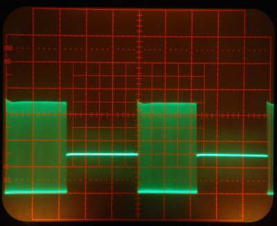
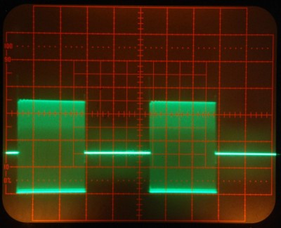
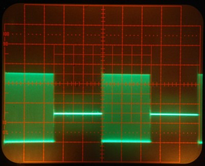
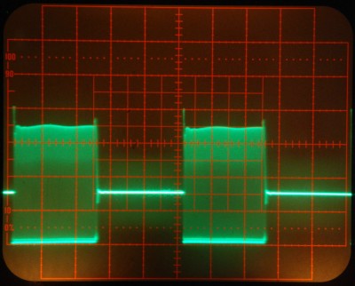
PA3 Output Waveforms at a Power Level of 300 Watts
The left side photos are of the PA3 output waveform across a 50-ohm dummy load.
The right side photos are of the PA3 output waveform across a Cheb 8-inch Phanotron tube.
The PA3 was coupled to the Phanotron tube using the 3.1 MHz link coil coupler.
The carrier frequency was 3.1 MHz. The modulation duty cycle was approximately 50%.
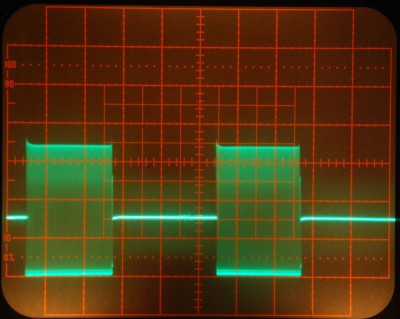
Modulation frequency 20 Hz.
Modulation frequency 2 KHz.
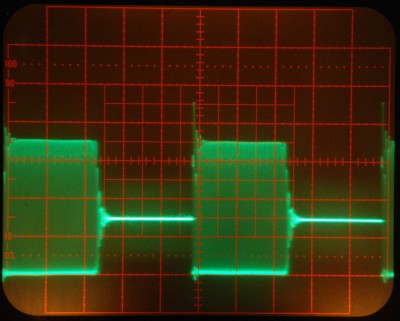
Modulation frequency 20 KHz.
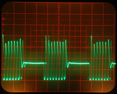
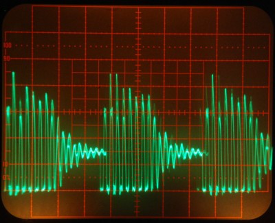
Modulation frequency 200 KHz.

This web site and all contents including pictures, text and diagrams is Copyright 2012 - 2026 by Ralph M Hartwell.